Undersea Fiber-Optic Cables: The Physical Engineering Behind Global Connectivity
Demystifying the Subsea Foundation of Global Bandwidth
Global cloud computing is often imagined as a satellite-driven service, with data crossing oceans through space before reaching a distant data center. In reality, submarine fiber-optic systems carry more than 95 percent of international data traffic, and some industry estimates place the share of intercontinental traffic above 99 percent. TeleGeography tracks more than 600 active and planned submarine cables, representing more than 1.5 million kilometers of cable in service worldwide. Satellites remain valuable for remote access, broadcast, timing, and resilience, but fiber provides the bandwidth, latency, and cost profile required for cloud platforms, financial networks, content delivery, artificial intelligence, and international enterprise traffic.
These systems operate in an environment that is mechanically hostile and operationally remote. At abyssal depths, hydrostatic pressure approaches 1,000 atmospheres, while cables encounter thermal gradients, sediment movement, seismic activity, steep seabed slopes, fishing activity, and ship anchoring near the coast. Continuous connectivity therefore depends on several engineering layers working together: a mechanically protected optical cable, pressure-tolerant repeaters, a high-voltage direct-current power-feeding system, accurately surveyed routes, controlled deployment equipment, and repair methods precise enough to recover and rebuild a damaged line. Research on the physical constraints of subsea infrastructure reinforces the central lesson for network architects: capacity is only useful when the complete physical system can survive its environment.
Anatomy of an Armored Conduit Across the Ocean Bed
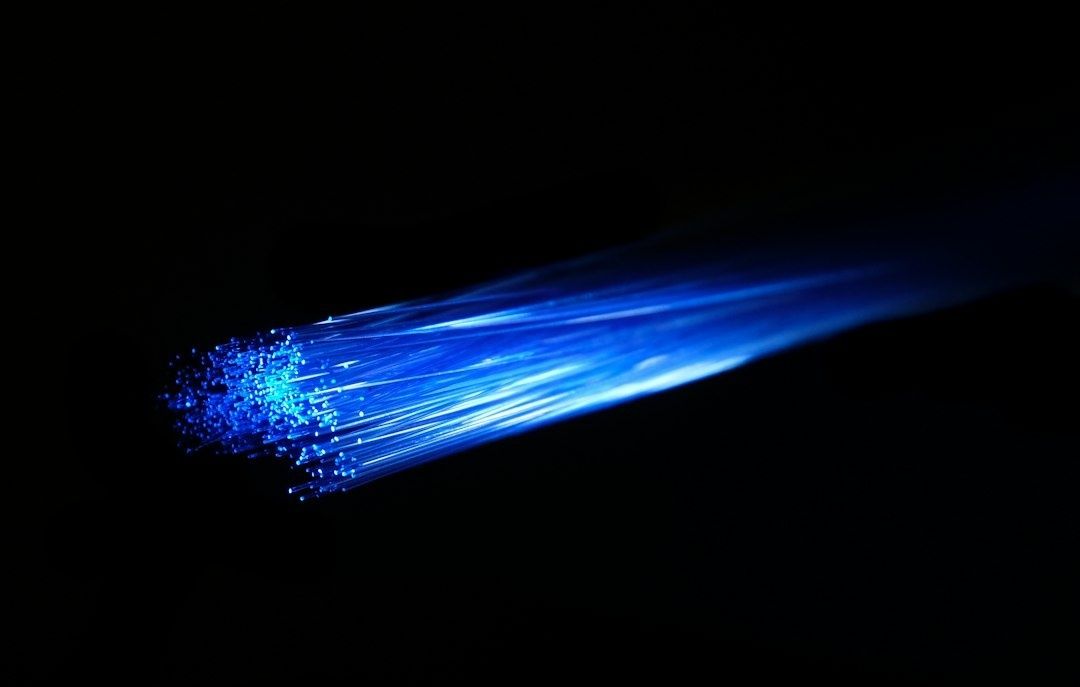
A submarine communications cable is not simply a glass fiber placed inside a plastic tube. Its cross-section is a coordinated mechanical and electrical system. At the center, one or more single-mode silica fibers guide optical signals over transoceanic distances. The fibers are commonly protected by coatings and a loose or controlled structure that limits tensile transfer, micro-bending, and water intrusion. Around that optical core, metallic strength members and conductive elements provide mechanical stability and a return path for the electrical power required by repeaters.
The copper conductor is particularly important because submerged repeaters are not independently powered. Power-feeding equipment at the landing stations applies high-voltage direct current through the cable conductor, with the sea acting as the electrical return path in the overall circuit design. The system is engineered for constant-current operation so that repeater power remains predictable even as cable resistance, distance, and fault conditions vary. This creates a demanding interface between the optical transmission design and the electrical power budget. A higher capacity system may require more optical channels, but every added active element and every longer span must remain compatible with the available voltage, current, insulation, and fault-management margins.
Cable construction changes substantially with water depth and external hazard. In deep water, where commercial fishing and anchoring are limited, lightweight cable minimizes suspended weight and reduces the tension required during laying. Near shore, the design becomes heavier. Steel wires, often arranged as single or double armor layers, resist abrasion, crushing, snagging, and localized impact from anchors or trawler gear. The cable may also be buried or given additional protection at landings and other high-risk sections. TeleGeography notes that cables are generally buried near shore and laid directly on the deep-ocean floor along routes selected to avoid hazards.
| Layer or subsystem | Typical material or construction | Protection purpose |
|---|---|---|
| Optical core | Single-mode silica fibers with protective coatings | Guides high-capacity optical signals while limiting attenuation and bend sensitivity |
| Strength and support elements | Metallic strength members and structural fillers | Controls tensile loading during manufacture, deployment, and recovery |
| Electrical conductor | Copper conductor with insulation system | Delivers high-voltage direct current to remote repeaters |
| Core insulation and bedding | Polymeric insulating and cushioning materials | Separates conductive components and limits mechanical stress transfer |
| Armor layers | Galvanized or otherwise protected steel wires | Resists impact, abrasion, crushing, fishing gear, and anchors in shallow water |
| Outer sheath | High-density polyethylene or comparable polymer | Provides water resistance, environmental protection, and a durable low-friction surface |
Understanding the physical constraints of subsea installations is essential when solving a deep-water deployment challenge. The practical decision is not simply whether to select a lightweight or armored cable. Route depth, seabed mobility, vessel capability, burial target, repair philosophy, landing-site exposure, and expected service life must be evaluated as one system. Prysmian”s integrated approach, which combines survey, route design, cable protection analysis, installation, maintenance, repair, and eventual decommissioning, illustrates why lifecycle engineering matters more than any isolated cable specification.
Electro-Optical Amplification Across Abyssal Depths
Light attenuation is unavoidable even in modern low-loss single-mode fiber. As photons travel thousands of kilometers, absorption, scattering, connector losses, splice losses, chromatic dispersion, polarization effects, and nonlinear interactions progressively reduce the usable signal margin. Passive compensation at the terminal cannot restore a signal that has fallen below the receiver and noise requirements. In-line repeaters are therefore installed at regular intervals, commonly tens of kilometers apart, to restore optical power along the route.
Modern repeaters generally use erbium-doped fiber amplifiers, or EDFAs. A short section of fiber containing erbium ions is illuminated by a semiconductor pump laser, typically operating near 980 nm or 1480 nm. The pump raises erbium ions into an excited state. When an incoming signal in the C-band passes through the doped fiber, stimulated emission produces additional photons at the signal wavelength, creating optical gain without converting the signal into an electrical data stream. This direct optical amplification supports wavelength-division multiplexing and avoids the speed, format, and power penalties associated with optical-electrical-optical regeneration.
The repeater must provide useful gain without allowing noise and spectral distortion to accumulate across the chain. Typical EDFA designs use redundant pump lasers, gain-flattening filters, optical isolators, monitoring paths, and paired amplifier sections for bidirectional transmission. Amplified spontaneous emission raises the noise floor, making optical signal-to-noise ratio a key end-to-end constraint. A system designer must therefore balance span length, launch power, channel count, modulation format, nonlinear penalties, repeater gain, and terminal receiver margin rather than maximizing any single parameter.
- Pressure housing: A sealed metallic vessel protects pumps, couplers, monitors, and control electronics from hydrostatic loads that can approach 1,000 atmospheres in the deepest operating regions.
- Optical gain path: Erbium-doped fiber and pump lasers provide gain across the selected transmission band while preserving wavelength-division multiplexed channels.
- Redundancy: Duplicate pumps and carefully managed optical paths improve the probability that the repeater will meet its design life despite component degradation.
- Power interface: The repeater converts the high-voltage, constant-current feed into controlled electrical power for optical and supervisory functions.
- Monitoring: Telemetry and supervisory wavelengths allow terminal equipment to evaluate repeater status, power conditions, and transmission performance.
Pressure-vessel design is not a cosmetic enclosure choice. Beryllium-copper and related corrosion-resistant metallic structures can provide the mechanical strength, conductivity, and dimensional stability needed for the repeater environment. Internal components must also tolerate thermal cycling, vibration during cable handling, long-term electrical stress, and the absence of routine physical access. At the landing station, power-feeding equipment must deliver thousands of volts of direct current over the span while controlling current, detecting insulation faults, and allowing safe maintenance. The electrical design is consequently inseparable from optical availability.
Subsea Route Engineering and Benthic Deployment Strategies
Route engineering begins long before a cable-laying vessel leaves port. Survey teams combine bathymetric mapping, side-scan sonar, sub-bottom profiling, geological information, and maritime-use data to identify a corridor with acceptable slope, sediment, obstruction, and hazard characteristics. The route must account for shipping lanes, existing cables, pipelines, protected habitats, fishing grounds, seismic fault zones, unstable sediments, and landing constraints. Exact route geometry is commercially and operationally sensitive, and public cable maps are often stylized rather than precise.
Seismic and geotechnical analysis helps distinguish a smooth, stable seabed from terrain likely to experience landslides, fault displacement, turbidity currents, or sediment scour. Nearshore sections receive especially careful treatment because they combine shallow water, strong human activity, mobile sediments, and complex permitting. Regulatory coordination is also part of the engineering workflow. NOAA guidance on international submarine cable matters demonstrates how cable projects intersect with maritime law, environmental review, hydrographic interests, and international coordination.
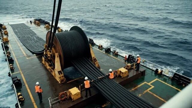
During deployment, the cable vessel uses dynamic positioning, controlled payout, and tension-management systems to maintain the planned track and catenary. Excessive tension can damage the optical core or transfer unwanted strain into the fibers, while insufficient control can create slack loops, seabed crossings, or unsupported spans. Ship motion, water depth, current, cable weight, and touchdown geometry are continuously modeled and monitored. The objective is not merely to place the cable on the seabed, but to place it with an acceptable residual tension and bend history.
- Route survey: Collect bathymetric, sonar, geophysical, and environmental data before final corridor selection.
- Hazard screening: Avoid or mitigate shipping, fishing, anchoring, unstable slopes, seismic activity, and existing infrastructure conflicts.
- Controlled lay: Use dynamic positioning and tension-controlled machinery to manage cable curvature and touchdown location.
- Burial: Deploy jet-plows or related burial tools where sediment conditions permit, commonly targeting protection of shallow-water sections to depths of several meters.
- Verification: Confirm burial, free spans, crossings, and protection measures using sonar, remotely operated vehicles, or post-lay surveys.
Jet-plow burial fluidizes or displaces seabed sediment so the cable settles into a trench, after which the seabed naturally or mechanically backfills. Burial depth depends on local hazard, sediment type, tool capability, and environmental requirements. It is not universally practical in hard rock, steep terrain, or deep ocean areas where direct laying may be the safer option. Environmental controls are therefore designed around local conditions, including turbidity management, protected habitats, seasonal restrictions, and coordination with hydrographic and coastal authorities. An installation that meets its optical specification but ignores benthic conditions can still become a long-term reliability risk.
Subsea Fault Diagnostics and Precision Maritime Splicing
When a cable fails, the first requirement is localization. Optical time-domain reflectometry sends a calibrated optical pulse into the fiber and measures backscattered light as a function of time. A discontinuity, reflection, or abrupt loss can indicate a fracture, severe bend, connector issue, or splice failure. By converting round-trip travel time into distance and correcting for fiber index, terminal engineers can estimate the fault location. Correlation from both ends, combined with electrical tests and route data, improves confidence before a vessel is mobilized.
Automated subsea OTDR equipment extends this diagnostic capability into remote environments. Compact, battery-powered systems such as the SOTDR described by C-Kore Systems can operate without external power, communications links, or direct ROV integration, allowing technicians to collect data offshore and review it remotely. The operational advantage is practical: better localization reduces search time, vessel fuel consumption, weather exposure, and the risk of disturbing an intact cable while attempting recovery.
- Confirm the event: Compare terminal alarms, optical performance, power-feed behavior, and OTDR traces to distinguish a fiber fault from terminal or equipment problems.
- Calculate the repair position: Reconcile measurements from both landing stations with the surveyed route and cable slack to define a recovery area.
- Mobilize the repair vessel: Secure permits, specialized grapnels, cable-handling equipment, spare cable, jointing hardware, and qualified personnel.
- Recover the cable: Use grapnels, lifting gear, and, where appropriate, a work-class ROV to locate, inspect, and bring the damaged section aboard.
- Prepare the ends: Remove damaged armor and sheath, stabilize the cable, identify fibers, and establish a controlled shipboard work area.
- Fusion splice the fibers: Align and join the 125-micron glass fibers with a precision fusion splicer, then verify insertion loss and reflectance.
- Rebuild the joint: Install the splice enclosure, restore strength members and conductors, seal the assembly, and perform electrical and optical qualification tests.
- Redeploy and verify: Lower the repaired section, recover appropriate slack, inspect the seabed position, and repeat end-to-end transmission tests.
Shipboard fusion splicing is a precision manufacturing operation performed under difficult logistical conditions. The fiber ends must be stripped, cleaned, cleaved, aligned, and fused in a controlled environment that limits dust, moisture, vibration, and handling errors. The splice itself is only one part of the repair. The rebuilt joint must also restore tensile continuity, electrical insulation, water blocking, pressure resistance, and the cable”s designed bend behavior. A low-loss optical splice is not a successful repair if the joint case later admits water or transfers stress into the fibers.
ROVs add an important inspection and intervention layer, particularly in deep water, strong currents, poor visibility, or complex seabed terrain. Cameras, sonar, USBL positioning, and station-holding controls can document the cable, burial condition, damage mechanism, and final placement while reducing diver exposure. Repair qualification typically includes optical loss testing, high-voltage insulation checks, continuity tests, pressure or immersion validation of the jointing system, and documentation against the applicable cable design and manufacturer procedures. The goal is to return the line to a service condition compatible with its remaining design life, not merely to restore traffic temporarily.
Engineering Long-Term Resilience into Benthic Telecommunications
Subsea network design is a continuous trade-off between optical capacity, electrical power, mechanical survivability, repairability, and route diversity. More channels and higher spectral efficiency can increase capacity, but they may tighten optical signal-to-noise, nonlinear, and power margins. Heavier armor improves protection in shallow water, yet increases cable weight, installation tension, and handling complexity. Longer repeater spacing can simplify the optical chain, but it demands lower-loss fiber, stronger terminal performance, or more advanced amplification. The correct architecture is therefore the one that closes every budget simultaneously: optical, electrical, mechanical, thermal, operational, and economic.
Future systems are expected to explore spatial division multiplexing, including multi-core or multi-mode fiber approaches, alongside more geographically diverse and decentralized routing architectures. Additional landing points, branching capability, automated traffic engineering, and independent cable corridors can reduce the effect of a single fault. These developments do not eliminate the need for robust physical construction. They increase it, because higher aggregate capacity makes each individual cable, repeater, landing station, and repair decision more consequential. For telecom architects and infrastructure engineers, the enduring lesson is clear: worldwide digital connectivity depends not only on sophisticated protocols and semiconductor systems, but also on the disciplined physical craftsmanship that keeps glass, copper, steel, pressure vessels, vessels, and seabed routes working together for decades.