

Synthesizing Inertia: How Grid-Forming Inverters Keep Renewables Stable
The Vanishing Flywheel and the New Physics of Grid Stability
Large synchronous turbogenerators historically supplied more than active power. Their rotating masses stored kinetic energy, resisted sudden frequency changes, contributed fault current, and established a stiff electrical reference for neighboring equipment. As gigawatt-scale coal, gas, hydro, and nuclear units are displaced by wind, solar, and battery resources connected through power electronics, that physical flywheel is disappearing from many transmission and distribution areas. The result is not simply a change in generation mix. It is a change in the dynamic physics that engineers must model, control, and validate.
Most conventional grid-following (GFL) inverters assume that an external source already provides a usable AC waveform. A phase-locked loop, or PLL, estimates grid angle and frequency, then commands the converter to inject current relative to that reference. This architecture is effective when the network is strong, short-circuit capacity is high, and synchronous machines dominate system behavior. It becomes less comfortable as grid strength falls. High Rate of Change of Frequency, low fault levels, voltage distortion, and rapid phase movement can cause PLL excursions, loss of synchronism, current-control saturation, and nuisance tripping.
Grid-forming (GFM) inverters address the architectural problem directly. Rather than waiting for a reliable angle to be detected, a GFM controller generates an internal voltage magnitude and phase angle, then regulates power exchange through that synthesized waveform. It behaves more like an autonomous voltage source than a commanded current source. This does not create energy from software, and it does not make a converter identical to a synchronous machine. It does, however, allow stored energy, plant controls, and network measurements to be coordinated so that frequency and voltage respond constructively during the first critical cycles of a disturbance.
- Physical inertia is being replaced by controllable electronic response.
- Low system strength makes PLL tuning and current control inseparable from network stability.
- GFM deployment must be evaluated through electromagnetic transient behavior, not only steady-state power flow.
Architectural Divergence Between Grid-Following and Grid-Forming Topologies
At the circuit level, a GFL inverter is commonly represented as a Norton-equivalent device: a controlled current source behind a comparatively high parallel impedance. Its control system measures the terminal voltage, estimates the angle with a PLL, and injects commanded active and reactive currents. The converter can deliver excellent power-quality performance in a strong network, but its reference depends on the very voltage that the system may be unable to maintain during a disturbance.
A GFM inverter is more naturally represented as a Thevenin-equivalent source: an internally generated voltage behind a dynamic series impedance. The voltage angle is produced by an oscillator, virtual synchronous-machine model, droop law, or related control structure. The series impedance may be physical, virtual, or a coordinated combination of both. This structure lets the converter regulate voltage and frequency while exchanging power with the grid, although it also creates difficult interactions with current limits, filter dynamics, protection, and other voltage-forming devices.
| Engineering characteristic | Grid-following inverter | Grid-forming inverter |
|---|---|---|
| Primary reference | Externally measured grid voltage and PLL angle | Internally synthesized voltage angle and magnitude |
| Equivalent behavior | Controlled Norton current source | Controlled Thevenin voltage source |
| Weak-grid sensitivity | High, particularly during PLL and current-loop interaction | Lower in principle, but strongly dependent on current limiting and impedance tuning |
| Synchronization | Fast tracking can become unstable under severe phase movement | Autonomous operation with resynchronization and power-sharing requirements |
| Planning emphasis | SCR, PLL bandwidth, current injection, and ride-through | Voltage-source interaction, virtual impedance, energy headroom, and EMT performance |
The mathematical vulnerability of the PLL becomes more pronounced as the short-circuit ratio declines. With a low SCR, sometimes approaching or below values such as 1.5 in challenging interconnection conditions, the voltage angle created by the inverter’s own current injection can materially affect the measured terminal voltage. The PLL then responds to a waveform partly shaped by its own action. Delays, filter resonances, negative-sequence voltage, and phase jumps can close an unfavorable feedback loop. The converter may lose phase tracking even when its nominal current and power commands remain within its steady-state limits.
For system planners, the distinction is not merely terminological. A large-scale study from Pacific Northwest National Laboratory and the University of Wisconsin developed dynamic models for both inverter types and integrated them into a three-phase distribution solver. The work, titled Modeling of Grid-Forming and Grid-Following Inverters for Dynamic Simulation, illustrates why unbalanced, islanded, and high-penetration networks require dynamic models rather than only static power-flow representations. GFM devices can improve voltage and frequency stability, but their controls must still be validated against the actual feeder and transmission impedances.
Digital Control Algorithms for Synthetic Inertia Emulation
The central VSM relationship is a digitally implemented form of the swing equation, commonly expressed as J dω/dt = Tm – Te – DΔω. Here, J represents virtual inertia, Tm is the commanded mechanical-equivalent torque, Te is electrical torque, D is damping, and Δω is the frequency deviation. In a converter, these quantities are control variables rather than literal mechanical torques. The algorithm integrates power imbalance into an internal frequency and angle, then uses inner voltage and current loops to realize the commanded waveform.
Droop control is a lighter alternative. An active-power frequency law adjusts frequency according to active-power error, while a reactive-power voltage law adjusts voltage magnitude according to reactive-power error. Droop is computationally efficient, easy to coordinate among parallel units, and familiar to utility planners. VSM control can provide a more explicit inertial response and damping representation, but it introduces additional states, parameters, and tuning dependencies. Neither approach is universally superior. The correct choice depends on network strength, energy availability, fault strategy, plant-level coordination, and the required response during the first few milliseconds.
- Define the desired voltage-forming behavior, including nominal voltage, frequency, droop slopes, damping, and permissible angle excursions.
- Implement the outer power-frequency and voltage-reactive-power controllers with explicit limits, anti-windup logic, measurement filtering, and digital delay models.
- Coordinate the outer loops with inner voltage, current, modulation, and protection controls so that inertial commands do not request physically unavailable power.
- Test phase jumps, frequency ramps, voltage dips, islanding transitions, and resynchronization in EMT simulation and hardware-in-the-loop environments.
- Validate interactions among multiple GFM units, GFL resources, synchronous machines, transformers, cable capacitance, and protection systems.
During a sub-cycle phase-angle jump, VSM control can produce a response shaped by its virtual inertia and damping states, whereas basic droop responds primarily to measured power or frequency error. VSM behavior may reduce abrupt angle acceleration, but excessive virtual inertia can slow settling or increase energy demand. Droop often provides a simpler and more predictable steady-state sharing characteristic, yet it may not provide sufficient immediate support during a severe excursion unless its bandwidth and power reserve are carefully designed.
Adaptive inertia addresses this trade-off by changing the effective virtual inertia as the disturbance evolves. A sigmoid-based strategy described in peer-reviewed adaptive inertia research increases or decreases the control response according to frequency deviation without relying on a noisy frequency-derivative signal. Nonlinear damping can similarly provide strong transient restraint without imposing excessive damping during normal operation. These methods are promising, but their stability must be demonstrated with digital delays, saturation, measurement noise, and realistic plant energy limits included.
Cross-vendor coordination is equally important. The U.S. Department of Energy’s UNIFI grid-forming inverter initiative focuses on common performance concepts and interoperability. For utilities, the practical value of such work is consistency: droop slopes, virtual-machine behavior, ride-through logic, and test procedures should be specified in observable performance terms rather than left as incompatible vendor-specific interpretations.
Semiconductor Physics and Thermal Margins Under Inertial Delivery
Synthetic inertia is an energy-delivery event, not merely a control signal. When a GFM inverter injects real power immediately, that energy may come from a DC-link capacitor, a battery, an ultracapacitor, or an upstream converter stage. The DC-link voltage falls as stored energy is discharged, while semiconductor conduction and switching losses rise with current. If the energy source cannot sustain the requested response, the controller must reduce the command before DC-bus undervoltage, modulation saturation, or uncontrolled shutdown occurs.
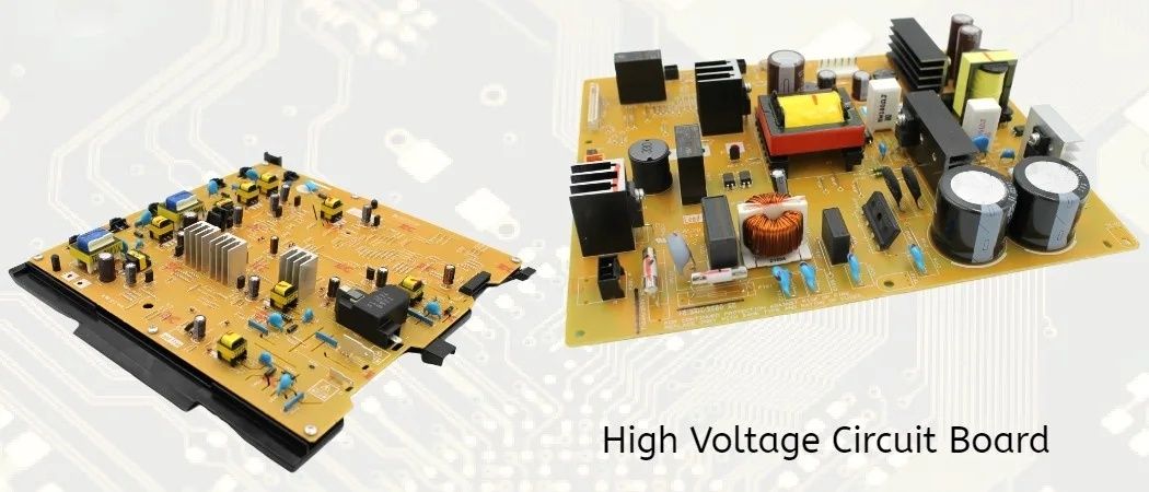
Silicon IGBTs remain attractive for high-power applications because of established packaging, rugged short-circuit behavior, and mature supply chains. Their switching losses and tail current can constrain high-frequency operation, and junction-temperature excursions must be managed through the complete thermal path from die to package, baseplate, heatsink, and cooling system. SiC MOSFETs can offer lower switching losses, higher practical switching speed, and strong dV/dt capability, but those advantages increase demands on gate-drive isolation, common-source inductance, electromagnetic compatibility, insulation coordination, and layout. Wide-bandgap devices are not a substitute for thermal design.
- Calculate semiconductor conduction and switching losses across normal operation, inertial overload, fault ride-through, and recovery.
- Track junction temperature rather than relying only on heatsink temperature; transient thermal impedance matters during short support events.
- Check dV/dt against gate-driver immunity, bearing-current risk, insulation stress, sensor isolation, and filter behavior.
- Verify that modulation, current limiting, and DC-link protection remain coordinated when the requested inertial power exceeds the available margin.
| Design area | Primary risk during inertial delivery | Practical verification |
|---|---|---|
| DC-link capacitor | Voltage collapse, ripple-current heating, and aging | Energy balance, ESR loss, voltage limits, and lifetime calculation |
| Power switches | Junction-temperature overshoot and repetitive thermal cycling | Electrothermal simulation with mission-profile loading |
| LC or LCL filter | Resonance excitation, damping loss, and control interaction | Impedance scan and EMT disturbance testing |
| Magnetic inductors | Core saturation during sudden voltage or angle shifts | Transient flux assessment and saturation margin review |
The output filter deserves particular attention. A sudden phase shift changes the voltage across filter inductors, potentially producing current ramps that are much steeper than normal power changes suggest. Core saturation reduces effective inductance and can push current rapidly toward the semiconductor limit. LCL filters add attenuation but also introduce resonance modes that can interact with the voltage loop, active damping, cable capacitance, and virtual impedance. A hybrid DC bus, combining high-power ultracapacitors with battery cells, can separate short-duration inertial power from longer-duration frequency support. The additional cost, balancing circuitry, protection, and lifecycle management must be justified by the required disturbance profile.
Current-Limiting Strategies and Fault-Ride-Through in Weak Networks
The hardware mismatch between synchronous alternators and inverters is fundamental. A synchronous machine can often supply several times rated current for a short period because electromagnetic and thermal time constants provide temporary fault capacity. Power semiconductors have much less tolerance for overcurrent. Depending on device, package, cooling, and duration, sustained operation near only modestly above nominal current can threaten junction temperature, bond wires, metallization, or magnetic components. Values such as 110 to 140 percent of rated current may already represent a serious control and thermal boundary for continuous or repeated events.
A GFM controller therefore cannot behave as an ideal voltage source during a fault. It must transition from voltage regulation toward controlled current limitation while preserving enough voltage-forming behavior to support recovery. Virtual impedance is one of the principal tools. By increasing a dynamically calculated series impedance, the controller reduces the voltage-source drive behind the fault and shapes positive- and negative-sequence current. The transition must be fast enough to protect hardware, yet smooth enough to avoid abrupt angle movement, current spikes, or destabilizing interactions with neighboring converters.
- Detect symmetrical and asymmetrical fault conditions using voltage, current, sequence components, and rate-of-change information.
- Increase virtual impedance or modify voltage references before current reaches the device protection threshold.
- Prioritize current components according to grid-code requirements, such as active-current recovery, reactive support, and negative-sequence limitation.
- Prevent integrator windup by coordinating voltage, power, modulation, and current limits with explicit anti-windup paths.
- Restore normal voltage-forming behavior through a controlled ramp, checking post-fault angle, DC-link voltage, and thermal state before releasing limits.
Fault recovery is often harder than fault entry. When the grid voltage returns, an inverter that has accumulated controller error may command an excessive voltage or current transient. A poorly coordinated limiter can also create post-fault angle instability, delayed active-power recovery, or transient overvoltage. Negative-sequence current control is especially important for unbalanced faults, but it consumes current capacity that cannot simultaneously be used for positive-sequence active power. The priority rules must therefore be explicit, deterministic, and tested over the full operating range.
Ride-through compliance must be treated as a system requirement rather than a single inverter checkbox. NERC guidance for inverter-based resources addresses momentary cessation, active-power frequency control, reactive-power voltage control, protection, frequency and voltage ride-through, PLL loss of synchronism, successive voltage dips, and grid-forming concepts. The relevant NERC reliability guidance should be read alongside applicable regional interconnection requirements and plant-specific protection settings. LVRT, negative-sequence injection, recovery ramps, and thermal limits must be reconciled so that compliance in one dimension does not create instability in another.
Executing the Modern Transition to Inverter-Stabilized Power Grids
Grid-forming inverters resolve an important limitation of high-renewable systems by replacing dependence on a pre-existing voltage reference with controlled voltage formation. They can synthesize inertial behavior, share active and reactive power, support islanded operation, and improve weak-grid performance. Those benefits are conditional, however. Software cannot provide unlimited energy, fault current, or thermal headroom. Every virtual-machine parameter and droop setting must be tied to measurable DC-side energy, semiconductor capability, filter behavior, and plant-level operating limits.
The practical transition requires coordinated engineering across three layers: digital control firmware, power-stage hardware, and system planning. Utilities and developers should move beyond simple steady-state capacity and SCR screening toward sub-cycle EMT metrics that expose PLL interaction, voltage-source coupling, current limiting, sequence behavior, thermal stress, and recovery performance.
- Specify GFM behavior through testable voltage, frequency, power-sharing, fault, and recovery requirements.
- Reserve energy and semiconductor thermal margin for the disturbance profile, not only for rated steady-state output.
- Validate VSM, droop, adaptive inertia, and virtual impedance controls together rather than as isolated functions.
- Use EMT and hardware-in-the-loop testing to assess weak-grid, unbalanced-fault, islanding, and multi-vendor interactions.
- Update interconnection studies so that sub-cycle performance is treated as a core reliability criterion.